SELF-DIAGNOSTICS
NOTE:Specific circuit and component testing procedures are not available. Manufacturer recommends using Portable Diagnostic Unit (PDU) for circuit and component fault diagnosis.
A/C-heater control panel contains a self-diagnostic function. A/C-heater control panel can store up to 5 A/CCM trouble codes at a time. When a system fault occurs, A/CCM stores information about the event in memory. Upon next ignition cycle, a beep will be heard and ER (error) will be displayed for 5 seconds on A/C-heater control panel.
RETRIEVING DIAGNOSTIC TROUBLE CODES
NOTE:Diagnostic Trouble Codes (DTC) can be retrieved using Jaguar Portable Diagnostic Unit (PDU) or a scan tool. If not available, A/C-heater control panel DTCs can be retrieved using on-board diagnosis incorporated in A/CCM. PDU diagnosis is more comprehensive than A/C-heater control panel diagnosis.
System Self-Diagnostic Test
A/C-heater control panel display will flash repeatedly indicating a list of 2-digit numbers. See DIAGNOSTIC TROUBLE CODE DEFINITIONS table. This procedure must be completed in order, through one complete cycle:
Display Element Check
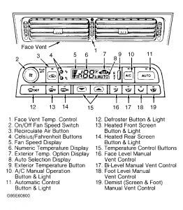
Turn ignition switch to OFF position. Simultaneously press and hold AUTO and RECIRC buttons. See Fig. 1 . Turn ignition switch to ON position while holding buttons. All display elements should illuminate and segments will flash on and off. If any display elements or segments do not light, an A/C-heater control panel or light fault is indicated.
Display Stored Numeric Trouble Code(s)
Press AUTO button. A 2-digit trouble code will be displayed. Codes 11, 15 and 21, will cause audible beep and ER to be displayed. If zero appears, there are no stored trouble codes, wait 30 seconds to allow system self-test to finish. A trouble code followed by a beep indicates an active trouble code. A trouble code not followed by a beep indicates an inactive trouble code stored in memory.
Scroll Through Trouble Code(s)
Press face button to display stored trouble codes. A maximum of 5 trouble codes can be stored.
Clear Stored Trouble Code(s)
Simultaneously press face and "R" (heated rear screen) buttons. It may be necessary to press face and "R" buttons to clear each stored trouble code.
NOTE:Actuator codes are not system trouble codes.
Initiate Actuator Check
Press RECIRC button to initiate actuator check. Actuator codes 20 through 27. Press fan to skip actuator check.
Exit System Self-Diagnostic Test
Press fan button to exit system self-diagnostic test. Press PUSH OFF button to restore normal operation.
*****************************************************************************************
DIAGNOSTIC TROUBLE CODE DEFINITIONS
DTC (Panel DTC) Component
.........(0)(1) Normal Operation
P0335 (.....) Engine Speed Input
B1250 (11) In-Vehicle Temperature Sensor
B1253 (11) In-Vehicle Temperature Sensor
B1254 (12) Ambient Temperature Sensor
B1257 (12) Ambient Temperature Sensor
B1258 (21) Solar Sensor
B1260 (21) Solar Sensor
B1262 (44) (2) Defrost Servo Motor
B1263 (45) (2) Center Vent Servo Motor
B1264 (46) (2) Foot Servo Motor
B1265 (43) (2) Cool Air By-Pass Servo Motor
B1266 (41) (2) Left Fresh/Recirculated Air Servo Motor
B1267 (42) (2) Right Fresh/Recirculated Air Servo Motor
B1268 (34) (3) Defrost Vent Feedback Potentiometer
B1271 (34) (3) Defrost Vent Feedback Potentiometer
B1272 (35) (3) Center Vent Feedback Potentiometer
B1275 (35) (3) Center Vent Feedback Potentiometer
B1276 (36) (3) Foot Vent Feedback Potentiometer
B1279 (36) (3) Foot Vent Feedback Potentiometer
B1280 (33) (3) Cool Air By-Pass Feedback Potentiometer
B1283 (33) (3) Cool Air By-Pass Feedback Potentiometer
B1284 (31) (3) Left Fresh/Recirculated Air Feedback Potentiometer
B1287 (31) (3) Left Fresh/Recirculated Air Feedback Potentiometer
B1288 (32) (3)Right Fresh/Recirculated Air Feedback Potentiometer
B1291 (32) (3) Right Fresh/Recirculated Air Feedback Potentiometer
B1292 (.....) Battery Voltage Supply Through A/C Isolate Relay
B1294 (.....) Battery Voltage Supply Through A/C Isolate Relay
B1297 (.....) Sensor 5-Volt Reference Voltage
B1298 (.....) Sensor 5-Volt Reference Voltage
B1299 (.....) Sensor 5-Volt Reference Voltage
B1355 (.....) Battery Voltage Supply
B1849 (24) Face Vent Differential Temperature Control
B1852 (24) Face Vent Differential Temperature Control
B1853 (.....) Aspirator Motor
B1856 (.....) Aspirator Motor
B1857 (.....) Ignition Switched (AUX/ON) Ground Signal
B1858 (23) (4) Refrigerant Dual Pressure Switch
B1861 (23) (4) Refrigerant Dual Pressure Switch
B1862 (22) Compressor Lock Signal
B1863 (.....) Sensor Signal Ground
B1946 (13) Evaporator Temperature Sensor
B1947 (13) Evaporator Temperature Sensor
B1948 (14) Coolant Temperature Sensor Signal
B1949 (14) Coolant Temperature Sensor Signal
B1966 (15) Heater Matrix Temperature Sensor
B1967 (15) Heater Matrix Temperature Sensor
B1968 (.....) Heater Pump
B1969 (.....) Compressor Clutch Circuit
U1263 (.....) Control Panel Serial Communication
U1264 (.....) Control Panel Serial Communication
(1)When there are no DTCs, WAIT 30 seconds for system self-diagnostic test to finish.
(2)Check for an open or short in motor drive circuit, or a sticking/jammed motor flap.
(3)Open or short in potentiometer feed circuit. At times, motor may overrun and set additional codes. Cycling ignition on and off 2 or 3 times may correct problem.
(4)Temperatures less than 32°F (0°C) may set false trouble code due to low refrigerant pressure. Temperatures greater than 95°F (35°C) may set false trouble code due to temporary high refrigerant pressure.
Repair faults before clearing DTC's
CLEARING DIAGNOSTIC TROUBLE CODES
To clear trouble codes, turn ignition to ON position. Simultaneously press face and "R" (heated rear screen) buttons. It may be necessary to press face and "R" buttons to clear each stored trouble code. Press fan button to exit system self-diagnostic test. Press PUSH OFF button to restore normal operation.